


The SmartPi has a wide range of interfaces for communicating with other devices.
These are:
- MQTT
- FTP
- Modbus TCP (RTU via external module)
- Energymeter protocol
- SmartPi Cloud
MQTT

- MQTT (switch): enables/disables data transmission.
- Broker scheme: drop-down list
ssl://,tcp://orws://– depending on how the broker can be reached. Example:tcp://for an unencrypted Mosquitto broker on the local network,ssl://for an encrypted broker andws://for WebSocket. - Url: address of the broker, e.g.
192.168.1.10ormqtt.example.com. - Port: e.g.
1883(standard for unencrypted MQTT) or8883(TLS). - User name / Password: access credentials for the broker, if it requires authentication. For the password, the eye symbol shows/hides the plain text.
- Topic: the MQTT topic under which the values are published, e.g.
smartpi/house. - Send interval (s): how often data is sent, in seconds.
0means "with every measured value" (i.e. as fast as the device measures); a value such as60sends only once per minute.
All fields are saved immediately whenever you change them – there is no separate Save button.
FTP
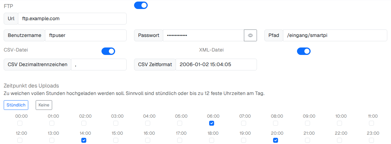
- FTP (switch): enables/disables the upload completely.
- Url: address of the FTP server, e.g.
ftp.example.com. - User name / Password: access credentials for the FTP server.
- Path: target directory on the server, e.g.
/incoming/smartpi. - CSV file / XML file: define the format in which data is uploaded – each can be switched on or off independently (both at the same time is also possible).
- CSV decimal separator: the character the CSV file uses as the decimal separator, e.g.
,(German) or.(English) – important so that the target spreadsheet reads the numbers correctly. - CSV time format: the date format of the time column, in Go notation, e.g.
2006-01-02 15:04:05for2026-09-17 14:30:00.
Upload time
The full hours at which data should be uploaded. Hourly or up to 12 fixed times per day are sensible.
- Hourly: selects all 24 hours at once.
- None: clears all selections (no more automatic uploads unless you activate individual hours again).
- Below are 24 individual checkboxes arranged in two rows of 12 hours each (00:00–11:00 at the top, 12:00–23:00 below, aligned in columns – e.g. 03:00 is directly above 15:00). Each ticked hour triggers an upload on the hour. Example: only
06:00and18:00ticked → upload twice a day, morning and evening.
All fields are saved immediately whenever you change them.
Modbus
The SmartPi has an integrated Modbus server via which the current measurement data can be retrieved.
Both Modbus TCP and Modbus RTU are available as protocols. If you want to use Modbus RTU, an RS485 interface is required. This can be, for example, the e.rs485+digital module or a USB stick or similar.

Modbus TCP
- Switch for activation.
- Address: the network address/port at which the Modbus TCP server can be reached, e.g.
:502(standard Modbus port).
Modbus RTU
Only possible with the SmartPi 3.1 or with an external RS485 interface (e.g. e.RS485+digital).
- Switch for activation.
- Address: the Modbus slave address of the device on the RS485 bus, e.g.
1. - Interface: the device path of the serial interface, e.g.
/dev/ttyUSB0or/dev/serial0.
All fields are saved immediately whenever you change them.
Modbus register map
The register map is identical for TCP and RTU. Only holding registers (function code 3, “Read Holding Registers”) return data – coils, discrete inputs and input registers always respond with 0.
- Start address:
0(protocol address) – i.e. 40001 in the classic 4xxxx notation. - Data type: each value occupies 2 consecutive registers (32 bits) as an IEEE 754 floating-point number (
float32), big-endian, without a scaling factor – the raw value is stored directly in the register (e.g.230.0for 230 V, not2300). - Write accesses (FC 5/6/15/16) are accepted, but are immediately overwritten with the current measured value in the next measurement cycle (every second) – the registers are effectively read-only.
|
Address (0-based) |
4xxxx |
Value |
Type |
|---|---|---|---|
|
0–1 |
40001–40002 |
Current L1 (A) |
float32 |
|
2–3 |
40003–40004 |
Current L2 (A) |
float32 |
|
4–5 |
40005–40006 |
Current L3 (A) |
float32 |
|
6–7 |
40007–40008 |
Current neutral conductor (A) |
float32 |
|
8–9 |
40009–40010 |
Voltage L1 (V) |
float32 |
|
10–11 |
40011–40012 |
Voltage L2 (V) |
float32 |
|
12–13 |
40013–40014 |
Voltage L3 (V) |
float32 |
|
14–15 |
40015–40016 |
Active power L1 (W) |
float32 |
|
16–17 |
40017–40018 |
Active power L2 (W) |
float32 |
|
18–19 |
40019–40020 |
Active power L3 (W) |
float32 |
|
20–21 |
40021–40022 |
cos(φ) L1 |
float32 |
|
22–23 |
40023–40024 |
cos(φ) L2 |
float32 |
|
24–25 |
40025–40026 |
cos(φ) L3 |
float32 |
|
26–27 |
40027–40028 |
Frequency L1 (Hz) |
float32 |
|
28–29 |
40029–40030 |
Frequency L2 (Hz) |
float32 |
|
30–31 |
40031–40032 |
Frequency L3 (Hz) |
float32 |
|
32–33 |
40033–40034 |
Energy consumption L1 since last measurement (Wh) |
float32 |
|
34–35 |
40035–40036 |
Energy consumption L2 since last measurement (Wh) |
float32 |
|
36–37 |
40037–40038 |
Energy consumption L3 since last measurement (Wh) |
float32 |
|
38–39 |
40039–40040 |
Energy feed-in L1 since last measurement (Wh) |
float32 |
|
40–41 |
40041–40042 |
Energy feed-in L2 since last measurement (Wh) |
float32 |
|
42–43 |
40043–40044 |
Energy feed-in L3 since last measurement (Wh) |
float32 |
|
44–45 |
40045–40046 |
Balance L1–L3 (Wh) |
float32 |
|
46–47 |
40047–40048 |
Power factor L1 |
float32 |
|
48–49 |
40049–40050 |
Power factor L2 |
float32 |
|
50–51 |
40051–40052 |
Power factor L3 |
float32 |
Energymeter protocol

- Switch for activation.
- Energymeter multicast address: the multicast group address via which the protocol is sent, e.g.
239.12.255.254(SMA standard address – if in doubt, do not change). - Energymeter multicast port: the corresponding port, e.g.
9522(SMA standard port). - Serial number: the serial number with which the SmartPi identifies itself as an Energy Meter. It must be unique on the network, e.g.
1234567890. - SusyID: the device type identifier of the emulated SMA device, e.g.
270(SMA Energy Meter).
These values are only relevant if another device (inverter, storage system) expects exactly this protocol – if in doubt, leave the default values.
All fields are saved immediately whenever you change them.