



LAN + RS422 + RS485
Power reduction
cos phi
RS422
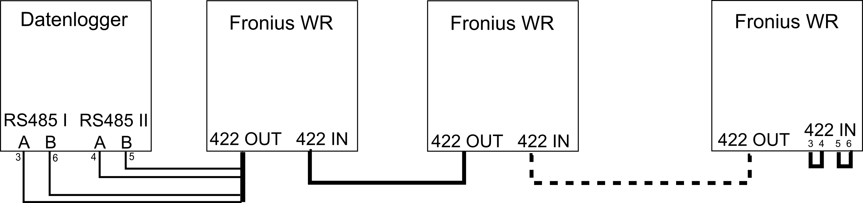
An RS422 connection requires 2 RS485 interfaces on the e.manager.
Connect the inverters to each other using a patch cable. Make sure that you always connect OUT to IN.
On the last inverter, connect wires 3 and 4 together, and wires 5 and 6 together.
Cut open the cable from the last inverter to the e.manager and connect the individual wires to the e.manager as follows.
e.manager RS485 I terminal A <=> PIN 3 (green-white)
e.manager RS485 I terminal B <=> PIN 6 (green)
e.manager RS485 II terminal A <=> PIN 4 (blue)
e.manager RS485 II terminal B <=> PIN 5 (blue-white)
Device address
Enter a unique address between 1 and 99 here.
Setup
   Inverter number (IG-NR)
Protocol
Enter a unique address between 1 and 99 here.
Setup (press Enter, Standby is displayed, then immediately press the Menu key 5 times)
The numeric code is: 22742

DATCOM (MIXmode)
   Protocol type (MODE)
Select the communication protocol “Interface” or IFP here
Baud rate
Only required for IG Plus and CL devices. Set 19200 baud here.
Setup
   MIXmode
      MODE
         IFP
RS485
Connect the inverters to each other using a patch cable. Make sure that you always connect OUT to IN.
On the last inverter, connect wires 3 and 4 together, and wires 5 and 6 together.
Connect the Datamanager of the last inverter to the e.manager.
Device address
Enter a unique address between 1 and 99 here.
Leave all other settings of the RS422 connection unchanged (protocol: Solarnet).
Setup
   Inverter number (IG-NR)
Datamanager
Connect to the Datamanager. All inverters must be visible in the Datamanager.
Activate Modbus.
Data export via Modbus:                 rtu
Baud rate:                              9600
Parity:                                 none
SunSpec Model Type:                     float
Inverter control via Modbus:            active
LAN
In this variant, all inverters are addressed directly via an IP address.
Device address
The address must be set to 1
Ethernet
Enter a unique address between 1 and 99 here.
Communication settings
Data export via Modbus:                 tcp
Inverter control via Modbus:            active
JSON:                                   active
Modbus ID:                              1
Solar API:                              active
LAN + RS422
In this variant, only one inverter is addressed directly via an IP address; the other inverters are then queried via RS422.
Connect all inverters via RS422 (see Fronius manual).
The first inverter is connected via LAN to the e.manager or router.
Device address
Assign a unique RS422 ID to each inverter. The IDs must start at 1 and be consecutive!
Leave all other settings at their defaults.
Ethernet
Enter a unique address between 1 and 99 here.
Communication settings
Data export via Modbus:                 tcp
Inverter control via Modbus:            active
JSON:                                   active
Modbus ID:                              1
Solar API:                              active