


The 0-10V output module adds four voltage outputs from 0 to 10 V to the SmartPi or the e.manager. You can use them, for example, to control inverters, immersion heater controllers, heat pumps or fans with a 0-10V control input.
This help page explains how to set up and use the module. An example shows how the 0-10V OUT module can be controlled using Node-RED.

The module at a glance
| Outputs | 4 voltage outputs, 0–10 V |
|---|---|
| Numbering | as on the circuit board, from left (1) to right (4) |
| Resolution | 12 bit, approx. 3 mV per step |
| I2C address | 0x60 (factory default) |
| Power-up values | After power-up, the outputs deliver their stored power-up values; factory default 0 V. |
The I2C address of the 0-10V module is not set via a jumper but is stored in the chip. The factory default address is 0x60.
The 4-20mA output module also has the address 0x60 by default. If you use both modules together, set the 4-20mA module to 0x61 using the jumper.
If you want to operate more than one 0-10V module on a SmartPi, please state this when ordering. The modules will then be supplied with different addresses.
Creating an API token
Node-RED accesses the module via the SmartPi API and requires an API token for this.
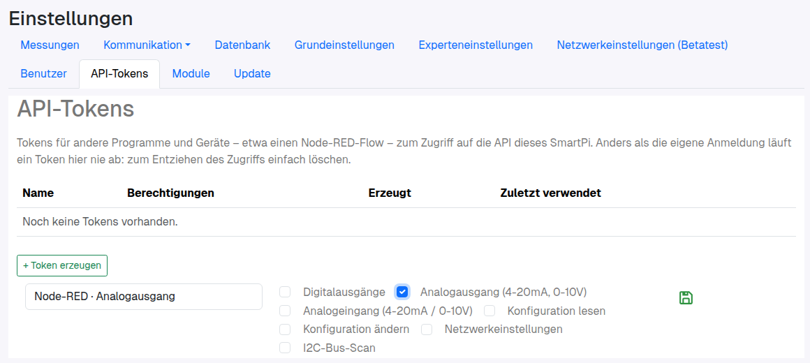
- In the SmartPi web interface, open Settings → API tokens.
- Click + Generate token and enter a name, e.g. Node-RED · Analogue output.
- Tick Analogue output (4-20mA, 0-10V) and save using the floppy disk icon.
- Copy the token displayed. You will enter it in the Node-RED node in a moment.
Setup in Node-RED
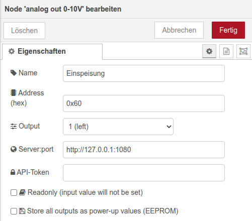
Drag the analog out 0-10V node (SmartPi category) from the node palette on the left into the workspace. Double-click it to open the settings window.
- Name: Freely selectable name for the node, e.g. Feed-in.
- Address (hex): I2C address of the module, factory default
0x60. - Output: The output that the node sets:
- 1 (left) to 4 (right): always this output
- from msg.topic (1-4): The output is supplied with each message in
msg.topic(see Multiple outputs with one node below). This is the default setting. - all: all four outputs at once
- Server:port: The address and port on which the SmartPi software is running. If Node-RED is used on the SmartPi, nothing needs to be changed here. If Node-RED is used on another computer, the IP address of the SmartPi must be entered here.
- API-Token: The token you generated as described above.
- Readonly: If this box is ticked, no values are set. Each message then only reads out the current voltages.
- Store all outputs as power-up values (EEPROM): After setting, stores the current values of all four outputs as power-up values (see Power-up values).
The node outputs the voltage reported back by the module in msg.payload. In addition, msg.moduleStatus contains the complete status of all four outputs.
Example: Outputting feed-in power as a 0-10V signal
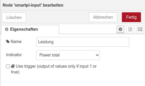
In the smartpi-input node, under Indicator, select the total power Power total. This passes the total power to the flow at the node's output.
The following boundary conditions apply:
- Feed-in measured by the SmartPi is shown as a negative value.
- Consumption is shown as a positive value.
- A feed-in power of 8,000 W is the maximum and should output 10 V.
- A feed-in power of 0 W (or consumption) corresponds to 0 V.

Drag the smartpi-input, function and analog out 0-10V nodes from the node palette on the left into the workspace and connect them as shown in the image.
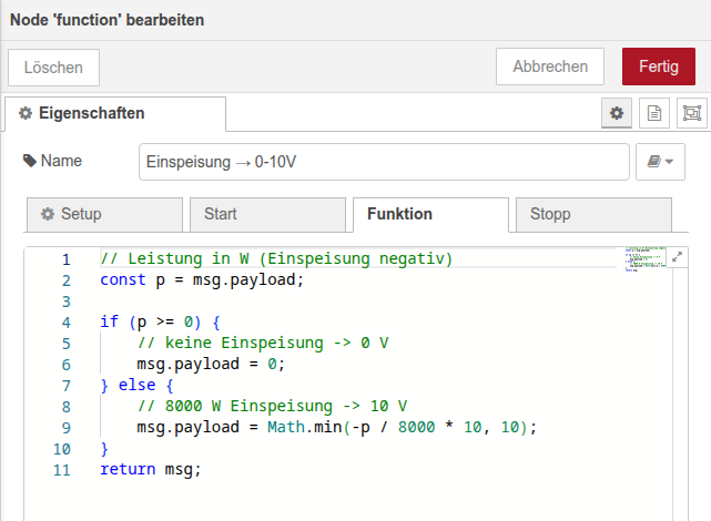
This outputs the total power to the flow at the module's output. The current power is converted to 0–10 V in the function node. If the power is not negative, 0 V is output. If the power is negative, it is inverted, divided by 8000 and multiplied by 10. This results in a signal of 0–10. Math.min(…, 10) ensures that no more than 10 V is output if the feed-in exceeds 8,000 W.
// power in W (feed-in negative)
const p = msg.payload;
if (p >= 0) {
// no feed-in -> 0 V
msg.payload = 0;
} else {
// 8000 W feed-in -> 10 V
msg.payload = Math.min(-p / 8000 * 10, 10);
}
return msg;
In the analog out 0-10V node, set Output to 1 (left) and enter the API token. Clicking Deploy starts the control.
You can use debug nodes to check whether the settings and calculations are correct. To do this, drag debug nodes from the palette on the left into the workspace and connect them to the outputs of the respective nodes. The debug output is opened at the top right using the bug icon.
You can also import the complete example flow into Node-RED via Menu → Import: beispiel-flow-0-10v.json. After that, you only need to enter the API token.
Multiple outputs with one node
A Node-RED node has only one input. So that you can still control all four outputs with one node, there is the setting Output: from msg.topic (1-4). In this case, the msg.topic of each message determines which output is set. The other outputs keep their value.
msg.topic = 2;      // output 2
msg.payload = 5.5;  // 5.5 V
return msg;
Connect several sources to the same node, with each source setting its own msg.topic, e.g. in a function or change node.
With Output: all, all four outputs are set at once. msg.payload can then be:
- a number that applies to all four outputs, e.g.
0 - a list in the order of the outputs, e.g.
[1.5, null, 10, 0](nullleaves the output unchanged) - an object with the output number, e.g.
{"2": 5}
Power-up values
After a power failure or restart, the outputs deliver their stored power-up values. The factory default is 0 V. Values set via Node-RED normally only apply until the next power-off.
If Store all outputs as power-up values (EEPROM) is ticked, the SmartPi stores the current voltages of all four outputs as new power-up values after setting. The chip can only store all four outputs together.
Calibration
The 0-10V output module works without calibration. However, due to component tolerances of the output amplifiers, the voltages may deviate from the set value by a few millivolts. Calibration allows the SmartPi to compensate for this deviation individually for each output.
Two measuring points (1 V and 9 V) are measured for each output. From these, the SmartPi calculates a factor and an offset and stores both. After that, every value set via Node-RED or the API is corrected automatically. Nothing needs to be changed in Node-RED for this.
The calibration is stored on the SmartPi, not on the module, and applies to the configured I2C address. If the module is connected to a different SmartPi, the calibration should be repeated.
What you need
- A voltmeter or multimeter (resolution of at least 1 mV in the range up to 10 V)
- A login to the SmartPi web interface with an administrator account
Step by step
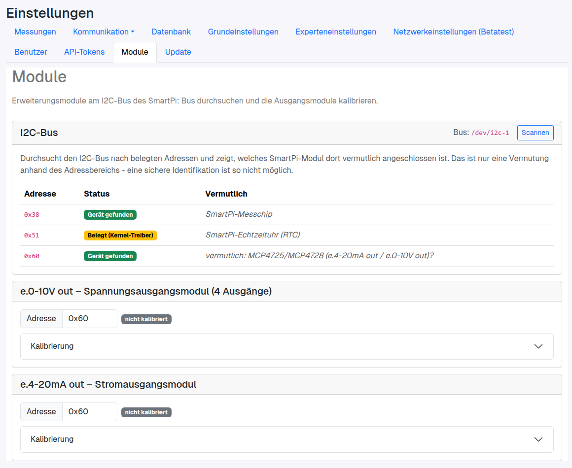
- Open the SmartPi web interface and go to Settings → Modules. At the top of the page, you can use Scan to check which addresses are in use on the I2C bus.
- In the e.0-10V out – voltage output module (4 outputs) section, check the address (factory default
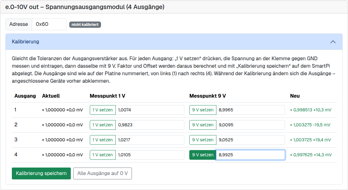
0x60). Confirm a changed address with Enter. Next to the address you can see whether the module has already been calibrated. - Expand the Calibration section. The Current column shows the stored calibration for each output (uncalibrated: × 1.000000 +0.0 mV).
- In the row for output 1, click Set 1 V. Measure the voltage between the terminal of output 1 and GND and enter the value in the field next to it, e.g.
1.0074. Both comma and point are allowed. - Click Set 9 V, measure again and enter the value, e.g.
8.9965. - Repeat this for outputs 2 to 4. The outputs are numbered as on the circuit board, from left (1) to right (4). You can also calibrate individual outputs only. Outputs without new measured values keep their previous calibration.
- The SmartPi displays the calculated calibration in the New column. If it shows “implausible – check terminal/input”, a value has usually been mistyped or measured at the wrong terminal. A maximum deviation of 10 % for the factor and a maximum offset of ±500 mV are permitted.
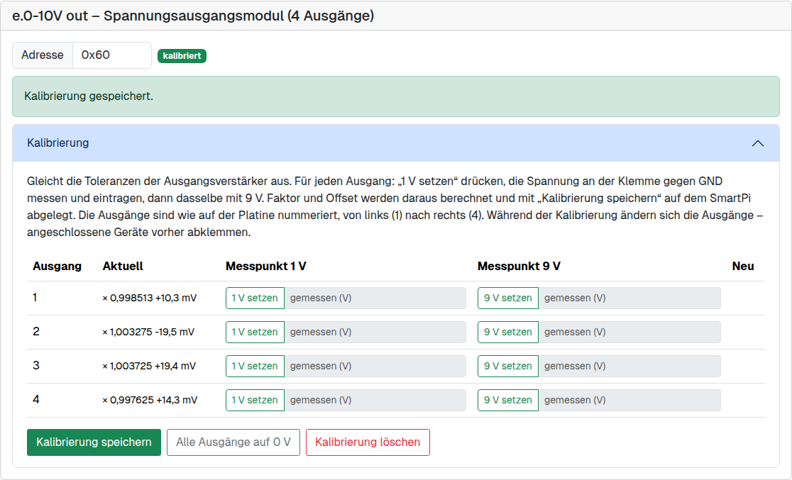
- Click Save calibration. The message “Calibration saved.” appears, calibrated is shown next to the address, and the new values are shown in the Current column.
- Click All outputs to 0 V and reconnect your devices.
Checking, recalibrating and deleting
- Check: After saving, set 1 V and 9 V again. The voltmeter should now display exactly these values to within a few millivolts.
- Recalibrate: Simply follow the procedure above again. An existing calibration does not need to be deleted first; the SmartPi takes it into account in the calculation.
- Delete: Delete calibration removes the correction for all four outputs. The outputs then work uncorrected again.
Troubleshooting
- Check: After saving, set 1 V and 9 V again. The voltmeter should now display exactly these values to within a few millivolts.
- Recalibrate: Simply follow the procedure above again. An existing calibration does not need to be deleted first; the SmartPi takes it into account in the calculation.
- Delete: Delete calibration removes the correction for all four outputs. The outputs then work uncorrected again.