


The 4-20mA output module adds a 4-20mA output to the SmartPi or the e.manager.
This help page explains how to set up and use the module.
An example shows how the 4-20mA OUT module can be controlled using Node-RED.

The module can be set to two different I2C addresses using a jumper.
This normally limits the maximum number of 4-20mA OUT modules to 2.
If you already have two modules connected and want to connect more, please state this when ordering.
Setup in Node-RED
Drag the analog out 4-20mA node from the node palette on the left into the workspace.
Double-click it to open the settings window.
- Name: Freely selectable name for the module (e.g. Feed-in).
- Address (hex): I2C address of the module (usually 0x60 or 0x61)
- Server:port: The address and port on which the SmartPi software is running. If Node-RED is used on the SmartPi, nothing needs to be changed here. If Node-RED is used on another computer, the IP address of the SmartPi must be entered here.
- API-Token: Enter the API token here that was generated in the settings under API tokens and enabled for this module.

Example: Outputting feed-in power as a 4-20mA signal
Insert your content hereIn this example, the feed-in power measured by the SmartPi is to be output as a 4-20mA signal.
The following boundary conditions apply:
- Feed-in measured by the SmartPi is shown as a negative value
- Consumption is shown as a positive value
- A feed-in power of 8,000 W is the maximum and should accordingly output 20 mA.
- A feed-in power of 0 W corresponds to 4 mA
Drag the nodes smartpi-input, function and smartpi analog out 4-20mA from the node palette on the left into the workspace


In the SmartPi-Input node, select the total power "Power total" as the input variable under Indicator.
This outputs the total power to the flow at the module's output.
The current power must be correctly converted to 4-20mA. This is done in the function node.
To do this, the node checks whether the power is negative. If it is not, 4 mA is output for 0 W.
If the power is negative, it is inverted, divided by 8000 and multiplied by 16. This results in an output signal of 0-16.
To get to 4-20, 4 is added to the signal.
The values from 4-20 are then passed to the smartpi analog out 4-20mA node, which controls the hardware expansion module.

Clicking Deploy starts the control.
Debug nodes can be used to output information on whether the settings and calculations are correct.
To do this, drag debug nodes from the palette on the left into the workspace and connect them to the outputs of the respective modules.
The debug output can be activated at the top right using the bug icon.

Calibration
The 4-20mA output module works without calibration. However, due to component tolerances, the actual output current may deviate slightly from the set value. Calibration allows the SmartPi to compensate for this deviation.
Calibration is carried out using two measuring points (4 mA and 20 mA). From these, the SmartPi calculates a factor and an offset and stores both. After that, every value set via Node-RED or the API is corrected automatically. Nothing needs to be changed in Node-RED for this.
The calibration is stored on the SmartPi, not on the module, and applies to the configured I2C address. If the module is connected to a different SmartPi or another module is used at this address, the calibration should be repeated.
What you need
- An ammeter or multimeter with a mA measuring range (resolution of at least 0.01 mA)
- A login to the SmartPi web interface with an administrator account
Step by step
- Connect the ammeter (mA measuring range) in series in the module's current loop.
- Open the SmartPi web interface and go to Settings → Modules.
At the top of the page you can use Scan to check which addresses are in use on the I2C bus. - In the e.4-20mA out – current output module section, enter the I2C address of the module (
0x60or0x61, depending on the jumper) and confirm with Enter. Next to the address you can see whether the module has already been calibrated. - Expand the Calibration section.
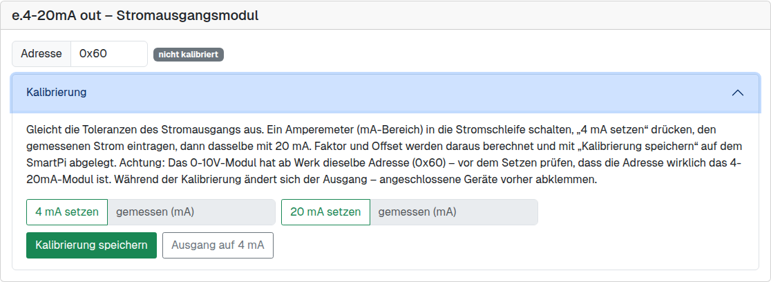
- Click Set 4 mA. Read the current on the ammeter and enter it in the field next to it, e.g.
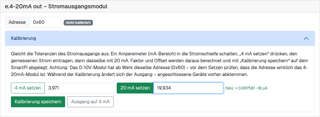
3.971. Both a comma and a point are accepted as the decimal separator. - Click Set 20 mA and enter this measured value as well, e.g.
19.934. - To the right, the SmartPi shows the new calibration (New: × factor offset). If it shows “implausible – check terminal/input”, a value has usually been mistyped or the meter is connected incorrectly. A maximum deviation of 10 % in the factor and a maximum offset of ±1 mA are permitted.
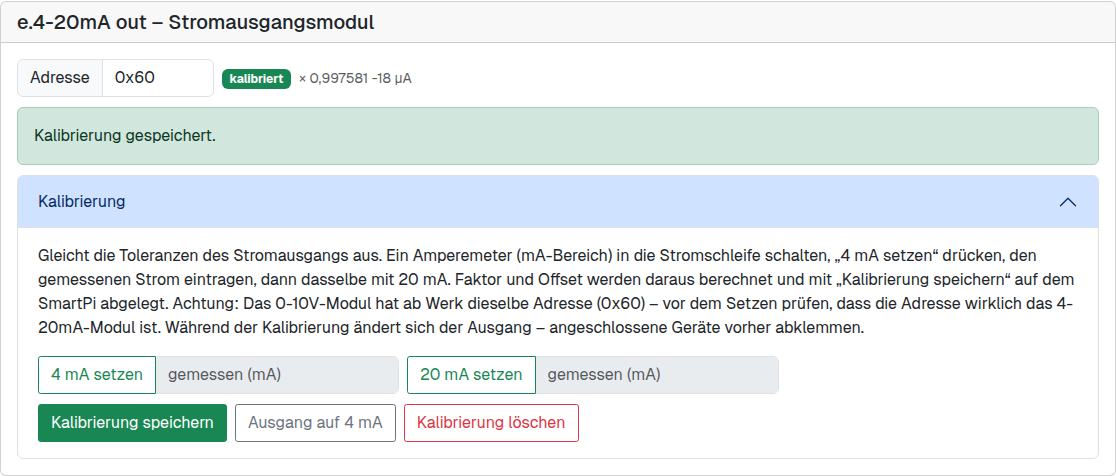
- Click Save calibration. The message “Calibration saved.” appears, and the address is now followed by calibrated with the factor and offset.
- Click Output to 4 mA, remove the ammeter and reconnect your device.
Checking, recalibrating and deleting
- Checking: After saving, set 4 mA and 20 mA once more. The ammeter should now show (almost) exactly these values.
- Recalibrating: Simply repeat the procedure described above. You do not need to delete an existing calibration first; the SmartPi takes it into account in the calculation.
- Deleting: Delete calibration removes the correction. The output then works uncorrected again.