



Inverters
Configure the inverters and other devices, such as electricity meters and sensors, and connect them to the e.manager via RS485 or LAN.
RS485: Connect the devices in a bus system: A to A and B to B.
Each device requires a unique ID.
LAN: Connect the devices to the e.manager via a switch or router.
Assign a static IP address to each device.
Ripple control receiver
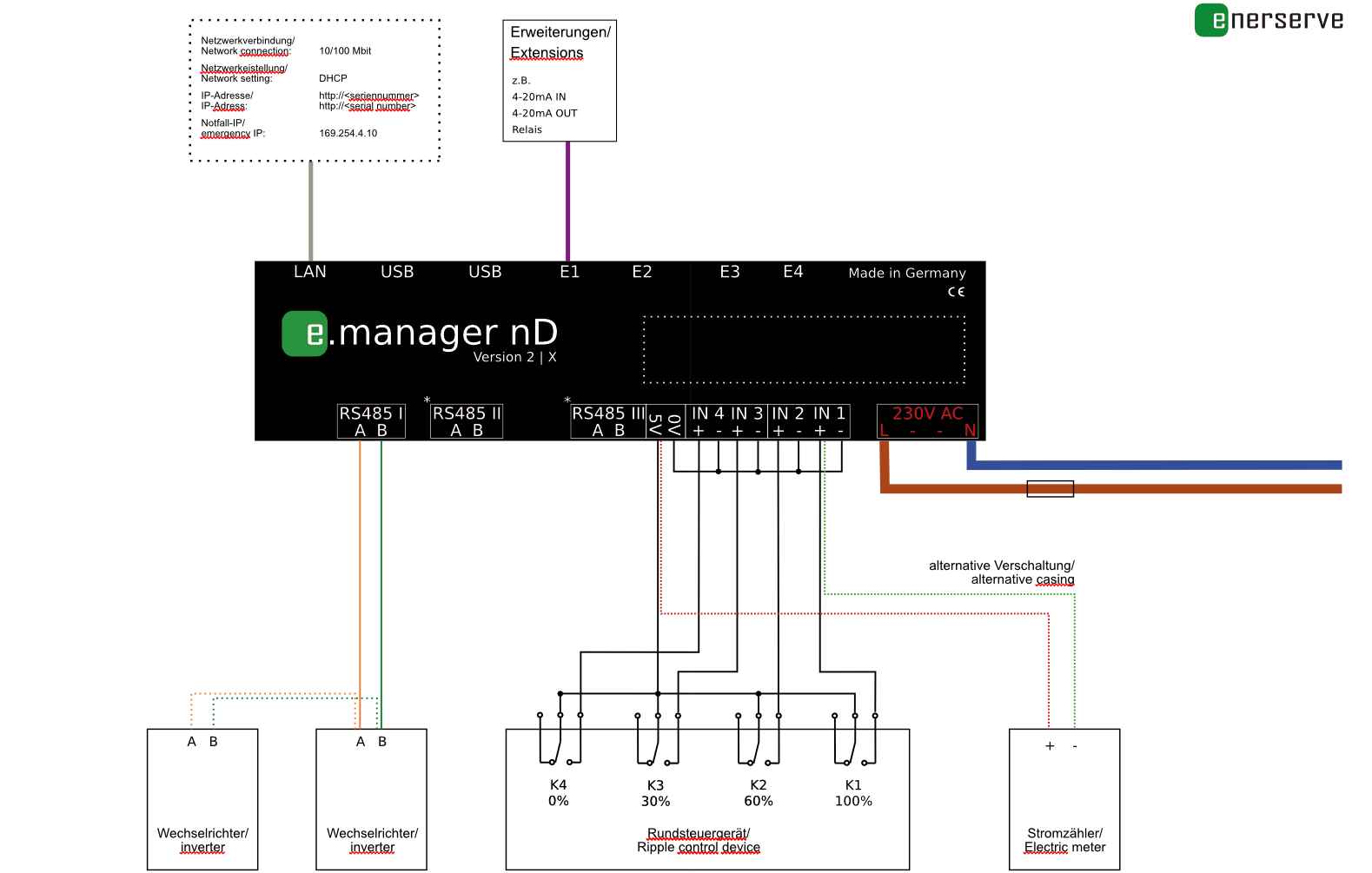
If you connect the ripple control receiver as shown in the example, no further configuration is required.
e.manager nD version 2: The inputs are galvanically isolated and can be operated at 5 V to 24 V DC. It is important that the negative inputs are bridged to ground potential.
e.manager mc version 2: The inputs are operated at 5 V.
Detailed instructions can be found in the quick start guides of the individual devices.
Network and power supply
Connect the e.manager to the router or to a switch.
Connect the e.manager nD version 2 or the e.manager mc version 2 to 230 V AC. We recommend using a separate miniature circuit breaker.
Web interface
For configuration, you need to access the web interface of the e.manager. You can find instructions here.
Device search
In the next step, you need to run a search for the inverters and other devices. You can find instructions here.
Checking measured values and configuration
After a restart, you can check the measured values. The home page shows, for example, the PV power and the current power reduction.
You can check the measured values of the individual inverters under Status => Devices.
Switch the 0% contact on the ripple control receiver and check on the home page whether the power reduction changes to 0% and whether the inverters ramp down.
Setting up the portal
To set up the system in the portal, you need the serial number and the MAC address. You can find this information:
- On the front panel of the e.manager
- On the side of the e.manager
- On the packaging
- On the enclosed stickers