



The SmartPi 3.0 expansion module
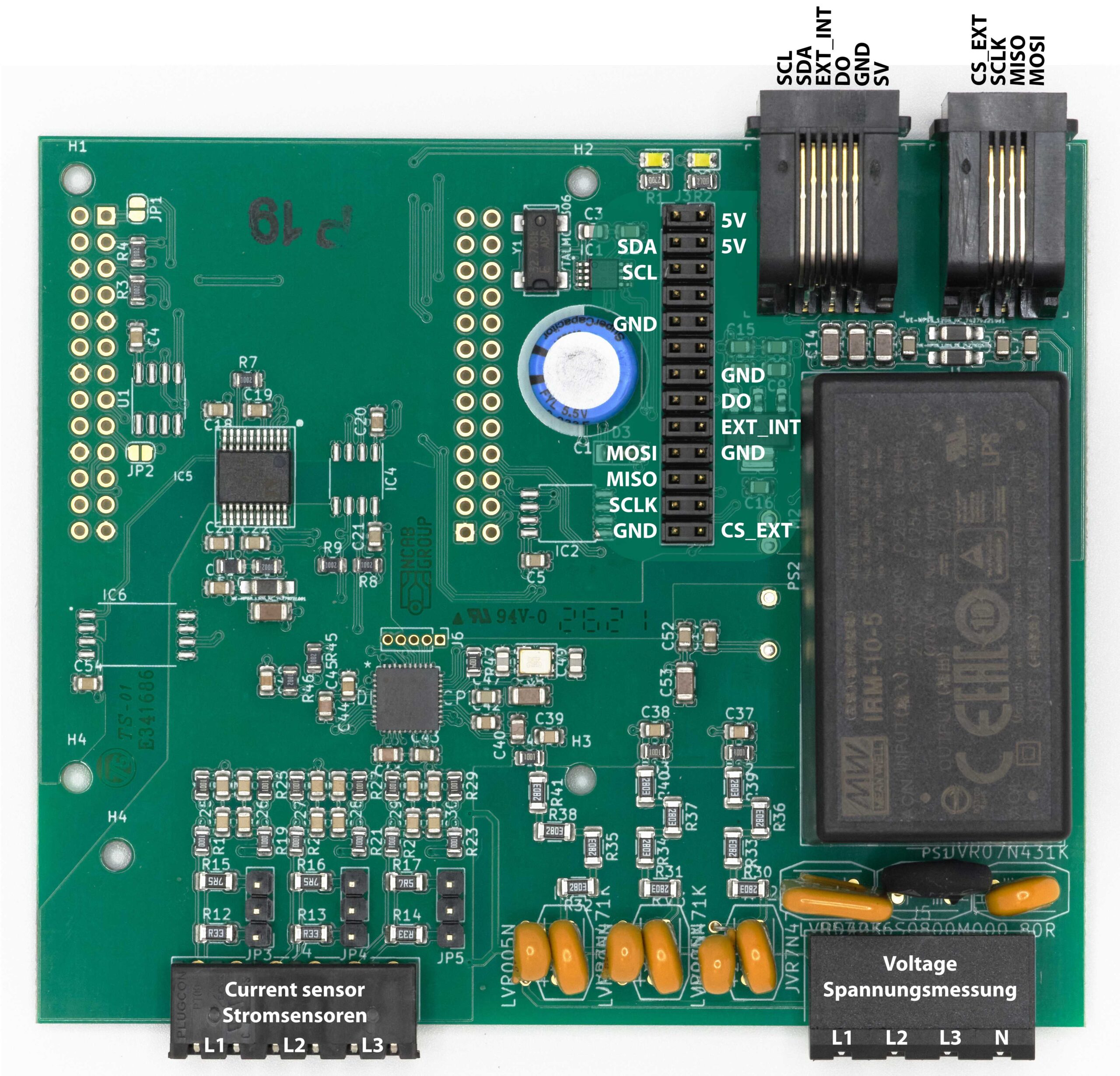
Figure 1: SmartPi 3.0 expansion board
Figure 1 shows the SmartPi 3.0 expansion module. The SmartPi 3.0 expansion module enables contactless current measurement via inductive current sensors using the Raspberry Pi. The SmartPi 3.0 expansion module can also be used to measure voltage, thereby transforming the Raspberry Pi into a fully-fledged smart meter.
To this end, the SmartPi 3.0 expansion module features 3 inputs for connecting inductive current sensors and 3 inputs for voltage measurement. The system is supplied with the required operating voltage via the L1 voltage measurement connection. A separate power supply is not required.
Connecting the SmartPi 3.0 to the Raspberry Pi
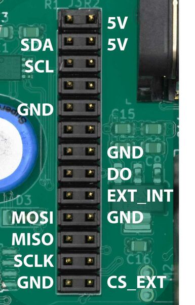
Figure 2: Connections used
The SmartPi expansion module connects via the Raspberry Pi’s GPIO port. The easiest way to connect it is using a 14-pin ribbon cable.
The Raspberry Pi is powered via the SmartPi expansion board. A power supply unit for the Raspberry Pi is therefore not required.
Figure 2 shows the labels for the connectors used.
| SmartPi | RaspberryPi |
|---|---|
| SDA | SDA / PIN3 |
| SCL | SCL / PIN5 |
| GND | GND |
| MOSI | SPI0_MOSI / PIN19 |
| MISO | SPI0_MISO / PIN21 |
| SCLK | SPI0_CLK / PIN23 |
| +5V | 5V / PIN2 / PIN4 |
| D0 | GPIO 23 / PIN16 |
| EXT_INT | GPIO 24 / PIN16 |
| CS_EXT | SPI0_CE1_N / PIN26 |
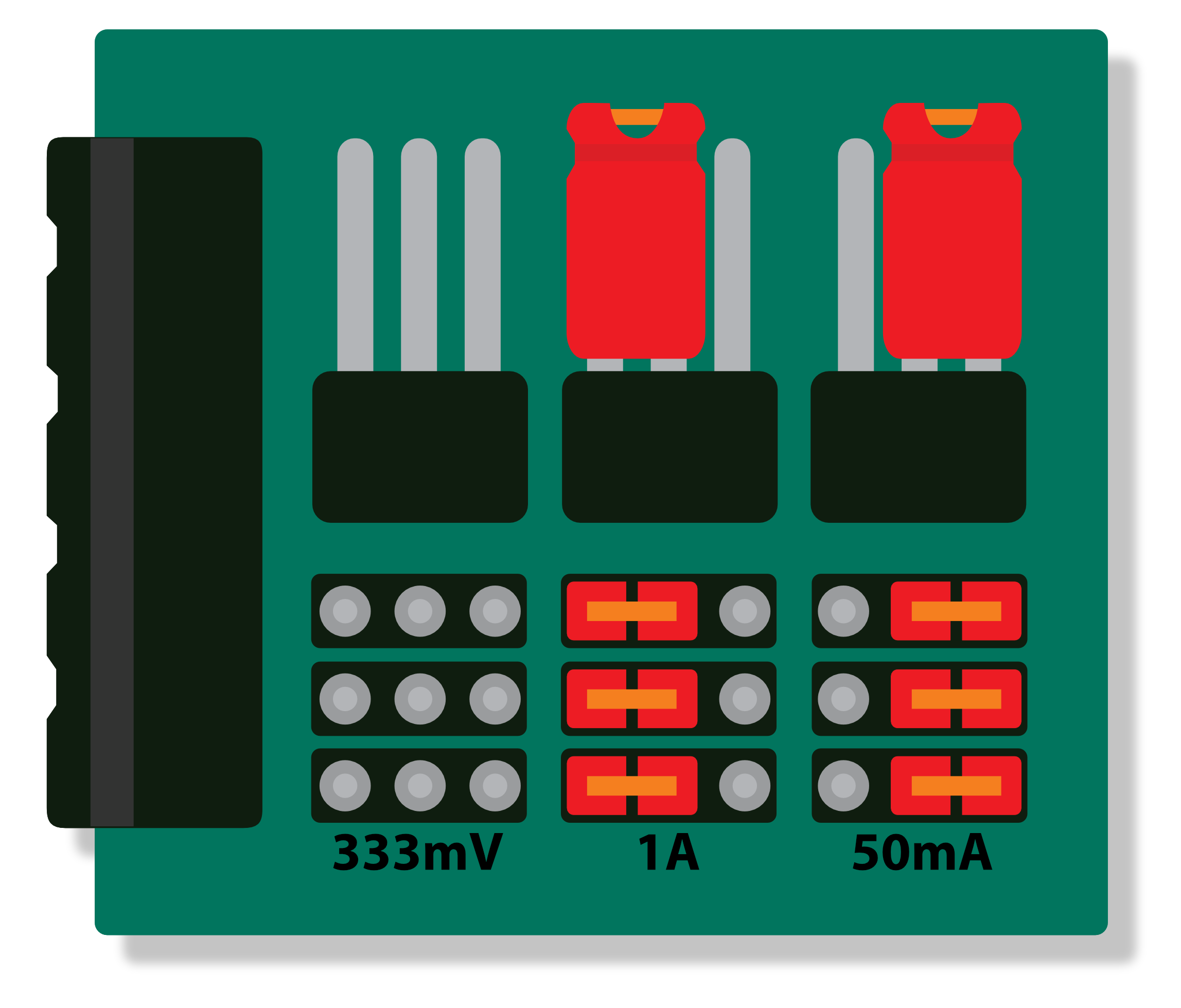
Figure 3: Jumper settings for selecting the correct secondary current
The SmartPi 3.0 is suitable for connecting both current transformers with a secondary current of 50 mA (e.g. SCT013-000) and current transformers with a secondary current of 1 A. Set the secondary current to match your current transformer.
Assembly the SmartPi 3.0
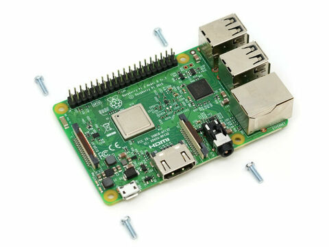
Screw the screws through the circuit board into the spacer bolts from above...
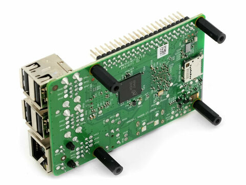
First, attach the spacer bolts to the Raspberry Pi. Hold the spacer bolts against the Raspberry Pi board from underneath...
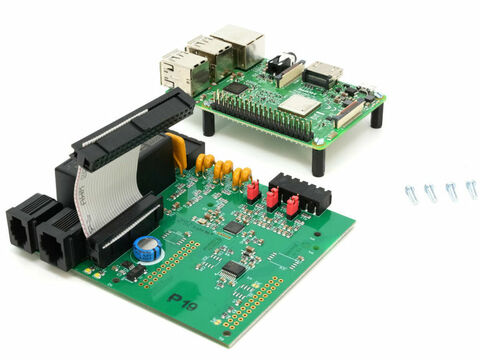
Connect the 14-pin ribbon cable to the SmartPi’s pin header. Please ensure that the cable is facing the battery. Secure the Raspberry Pi to the SmartPi.
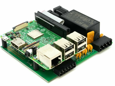
Next, plug the ribbon cable into the header on the Raspberry Pi.
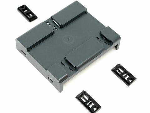
Next, insert the clips for the bracket from the inside out.
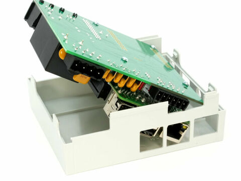
To install the SmartPi in the housing, please place the electronics inside the housing. Ensure that the connectors fit correctly.
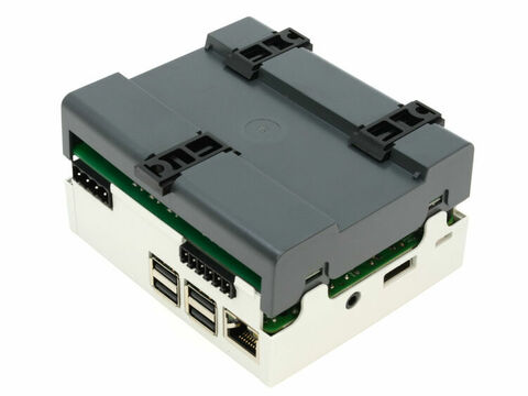
Next, place the lower shell on top and press it down. It may help to pry the tabs apart slightly with your fingernails.
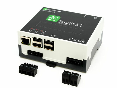
Insert the plugs into the sockets from the outside.
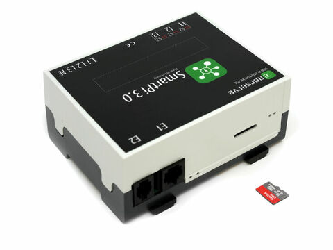
...then insert the SD card containing the operating system. That completes the installation.
Connecting the current and voltage meters

Figure 4: Connection diagrams for current and voltage measurement
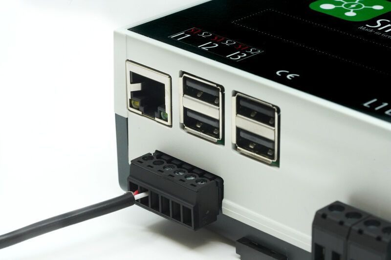
Figure 5: Connection of the SCT013-000
To connect the current measurement, the conductors of the individual phases are routed through the current sensors. Installation is very straightforward with clamp-on current transformers.
Please note that any arrow on the transformers indicates the reference direction. The ‘positive’ connection is routed to the right-hand terminal of the connection terminal block. Reversing the polarity of the connection cables is not a serious issue, but it will result in an incorrect display of the reference and measurement.
For the SCT013-000 current sensors (supplied), the red connection lead must be connected on the right-hand side (Figure 5).
Connect the test voltage to the voltage terminals. Ensure that L1 is on the left and the neutral conductor N is on the right. Take care not to reverse the polarity of the connections.
You can also use the SmartPi without voltage measurement.
To do this, you can set a default voltage in the software settings, which the SmartPi will use to calculate the power. Please note that in this case, power measurement is limited (no bidirectional measurement, reactive power only, no cos phi, no power factor).
A note on current measurement
The SmartPi measures electrical current in the same way as a clamp meter (also known as a current clamp, current clamp meter or clamp-on ammeter), i.e. indirectly. One advantage is that the circuit does not need to be disconnected and the measurement is contactless. The current I flowing through the conductor generates a magnetic field H, which runs in a ring shape around the conductor (Figure 7). The current is measured according to the transformer principle, with the conductor acting as the primary winding and the current sensor as the secondary winding. If a current sensor is placed around the conductor, the conductor’s magnetic field induces a current within it that can be measured (Figure 6). If current flows through two conductors in opposite directions, the resulting magnetic field cancels itself out, as the two magnetic fields are directed in opposite directions (Figure 8). The current sensor can then measure no current, or almost none.
The phase and neutral conductors must therefore not be clamped together using a current clamp. If you wish to measure the power consumption of an electrical appliance (e.g. a television), the individual conductors in the supply cable must be separated. The current clamp must then only be placed around the conductor through which the current flows into the appliance. If the current clamp is placed around the entire supply cable, the SmartPi will be unable to measure the power consumption.
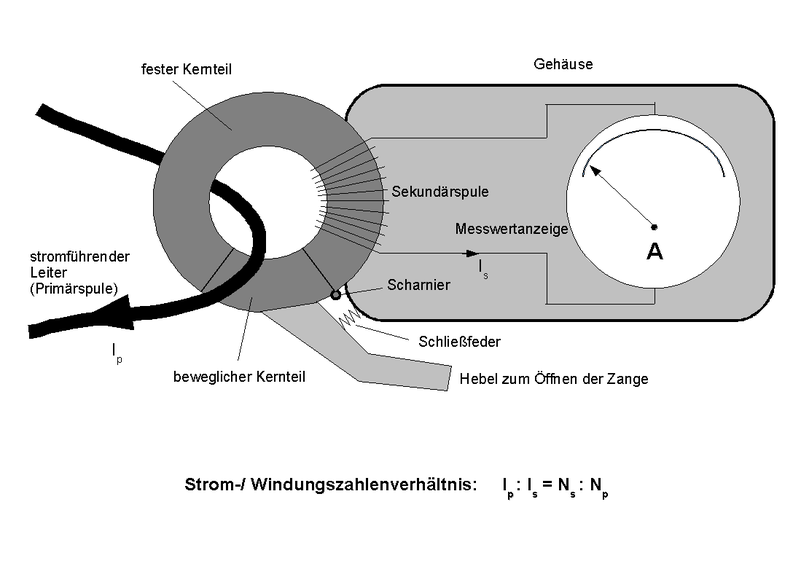
Figure 6: Principle of the current clamp for alternating current (Source: Wikipedia (©CC BY-SA 2.0 de))
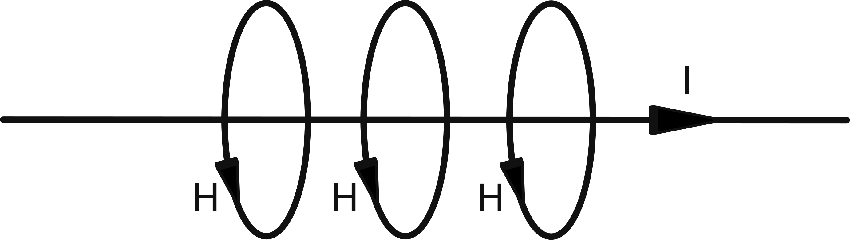
Figure 7: Magnetic field around a current-carrying conductor
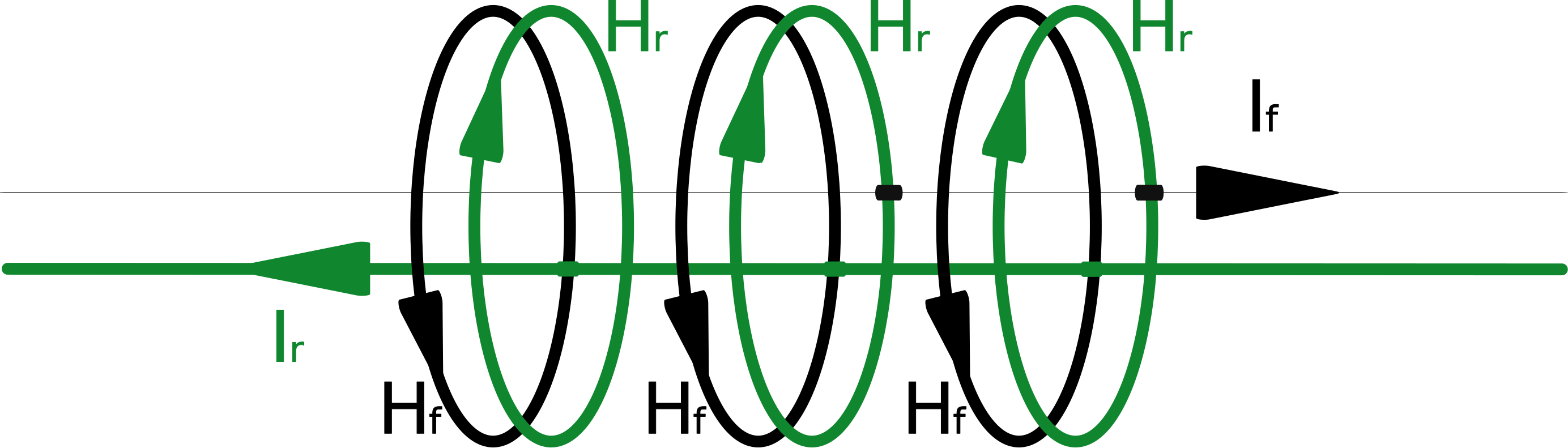
Figure 8: If current flows through two conductors in opposite directions, the net magnetic field cancels itself out.